







Why we tested it
A tapered shape looks logical: air widens gradually from the inlet towards the outlets, so it should flow more smoothly. That is why many partners see it as a must and a straight box as a compromise. We wanted to see what it comes to in numbers.
What we compared
Both models are identical except for the side walls. The straight one is 400 mm wide over its full depth. The tapered one is 400 mm at the front and 240 mm at the back, with each side wall angled by 17°. Height of 270 mm and depth of 260 mm are the same.
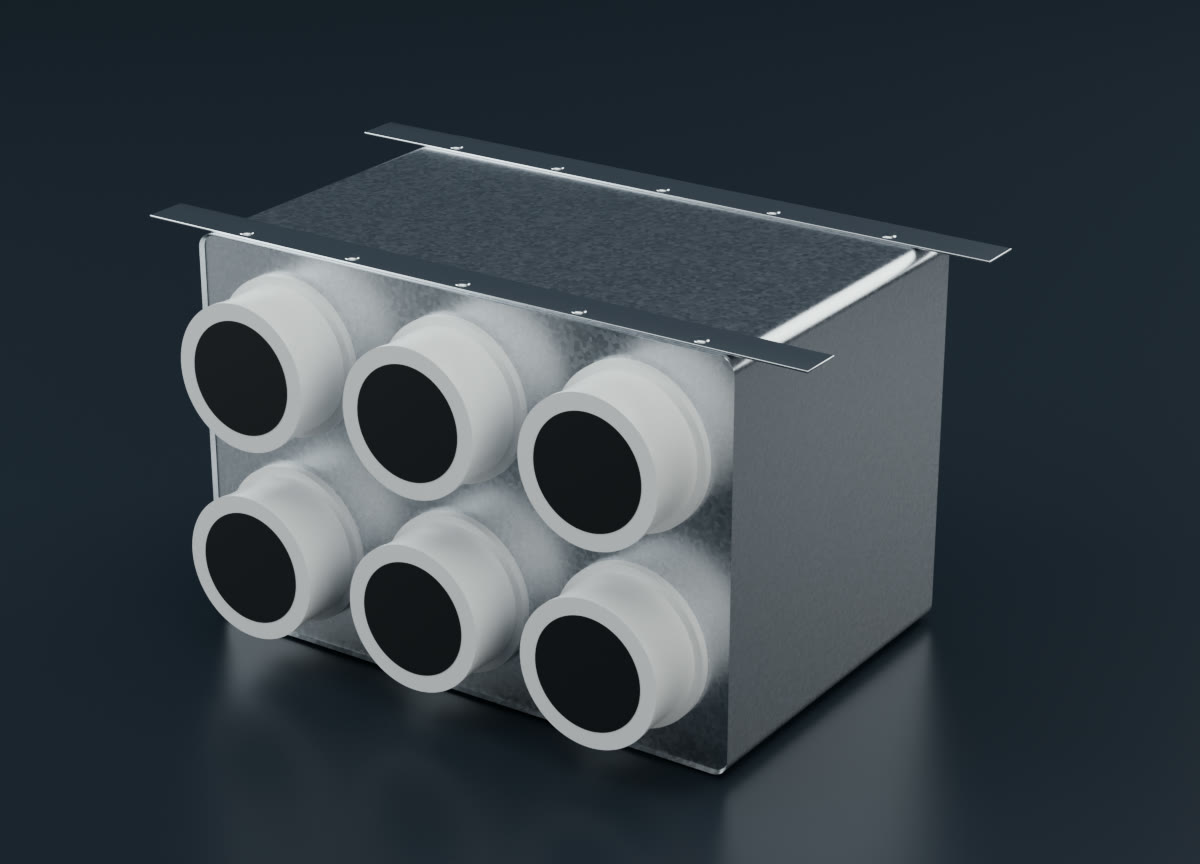
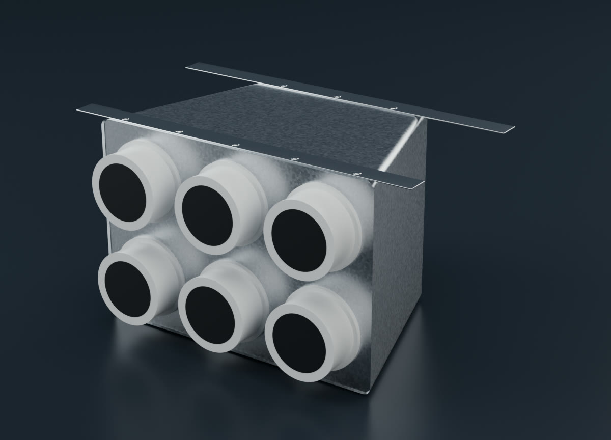
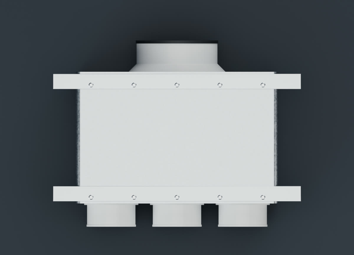
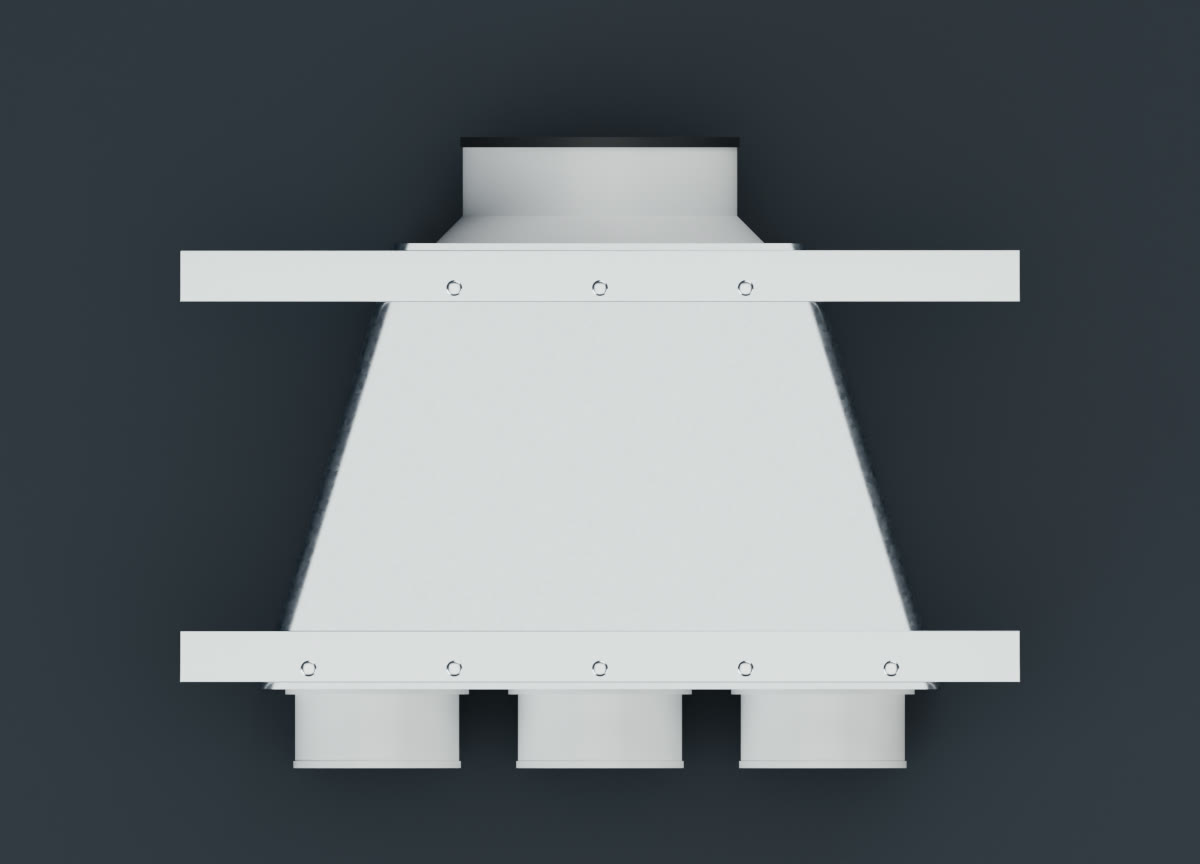
| Flow | 250 m³/h, supply, air 1.2 kg/m³, no temperature difference |
|---|---|
| Inlet | Ø160 duct, Ø152–155 neck |
| Outlets | 6 × DN90, 130 × 130 mm pitch, bayonets with damper, all open |
| After the bayonet | smooth pipe of Ø75 inner diameter, 300 mm long, discharging to equal pressure |
| Body interior | 10 mm lining included in the dimensions |
| Calculation | CFD with OpenFOAM, k-ω SST turbulence model, iteration average, 2 million cell mesh, 4.5 million cell check not completed |
Flow in both models
Particle colour shows velocity. The Ø160 inlet is on the left, the six outlets on the right.
Particles move in the averaged velocity field, so the video shows where the flow goes, not turbulent fluctuations. Slowed down 10×.
Result
| Total pressure drop | Straight | Tapered |
|---|---|---|
| Total | 16.25 Pa | 16.48 Pa |
| Ø160 duct and neck | 0.85 Pa | 0.85 Pa |
| Body up to bayonet entry | 3.69 Pa | 3.74 Pa |
| Bayonet with open damper | 3.94 Pa | 4.05 Pa |
| DN90 pipe and outlet | 7.77 Pa | 7.85 Pa |
| Centre outlets, average | 59 m³/h | 60 m³/h |
| Corner outlets, average | 33 m³/h | 32 m³/h |
The distributor body accounts for less of the total drop than the bayonets and pipes. The body is where tapering should show, and it changes there by less than 0.1 Pa. The table and videos come from the 2 million cell mesh, whose run completed. A check run on a 4.5 million cell mesh was interrupted after about 2,000 of 2,500 iterations. Its average from iteration 1,250 gave 16.8 Pa for the straight and 17.3 Pa for the tapered shape, with outlets at about 57 and 34 m³/h. The 0.6 Pa difference is larger than in the table, but the direction is the same: tapering does not reduce the drop. Absolute values differ between meshes by 0.5 to 0.8 Pa, so read them as a comparison, not as exact values.
Why tapering changes so little
The jet from the neck runs through the middle of the body straight at the bayonets and turns along the front wall towards the corner ones. The side areas hold only slow recirculation. Tapering removes exactly this slow volume: the body is about 21 % smaller, but the main flow stays almost the same.
The same flow in a 3D view
This view shows better how the flow splits between the upper and lower outlet rows.
What this means for installation
A tapered distributor is not a mistake. If it fits the space better or you like it, use it. Just do not expect tapering alone to give a noticeably lower pressure drop in a setup like this.
In this test more air goes to the centre outlets (59 m³/h compared to 33 m³/h at the corners) with both shapes. The ratio is affected by the short pipes in the model. In a real run the ductwork has more resistance, flows even out more and the damper handles the rest.
Where this result does not apply
- It applies to this size, 6 × DN90 and 250 m³/h. Other dimensions or flow rates may differ.
- Only the side walls are tapered, in one plane. We did not test a cone tapered in all directions.
- Noise was not evaluated.
- The pipes after the bayonets are only 300 mm long, the flow split in a long run will be more even.
FAQ
Should I stop using tapered distributors?
No. A tapered distributor works just as well. The result only says that tapering the side walls does not visibly reduce the drop by itself in this setup.
Does this also apply to a cone tapered in all directions?
We did not test that. We only compared tapered side walls at equal height.
What about noise?
Noise is not part of this comparison. We evaluated pressure drop and flow split.