







Why the air sticks to the ceiling
Most modern disc valves and ceiling diffusers do not blow the air straight down. They blow it sideways, just under the ceiling. Next to a flat surface the jet creates a low pressure and "sticks" to the surface. This is called the Coandă effect.
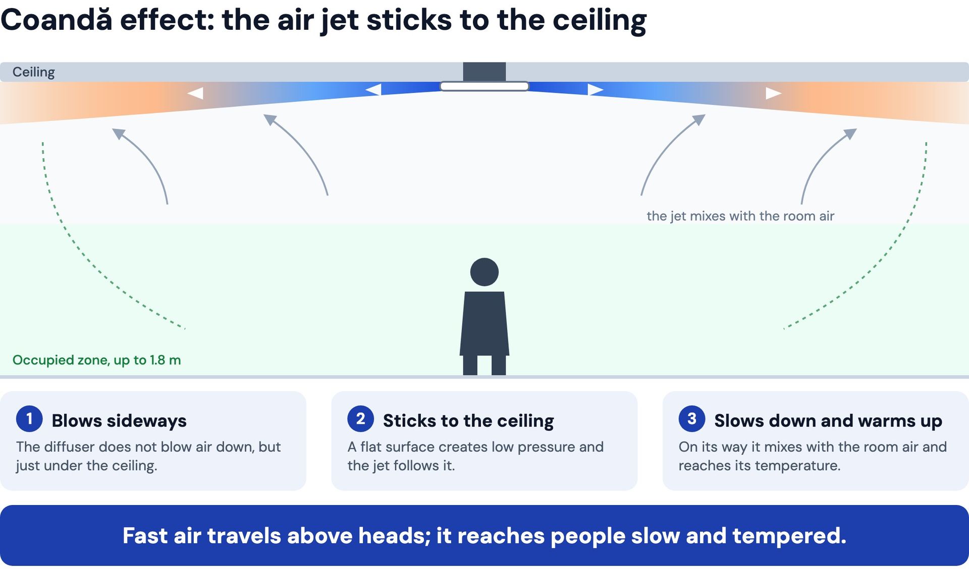
The benefit is simple: the fast and slightly cooler air travels above people's heads. On its way it slows down, mixes with the room air and reaches room temperature. By the time it gets to people, it is slow and tempered. However, the jet only stays on the ceiling until something blocks its path. Most often that is a wall.
What happens when the jet hits a wall
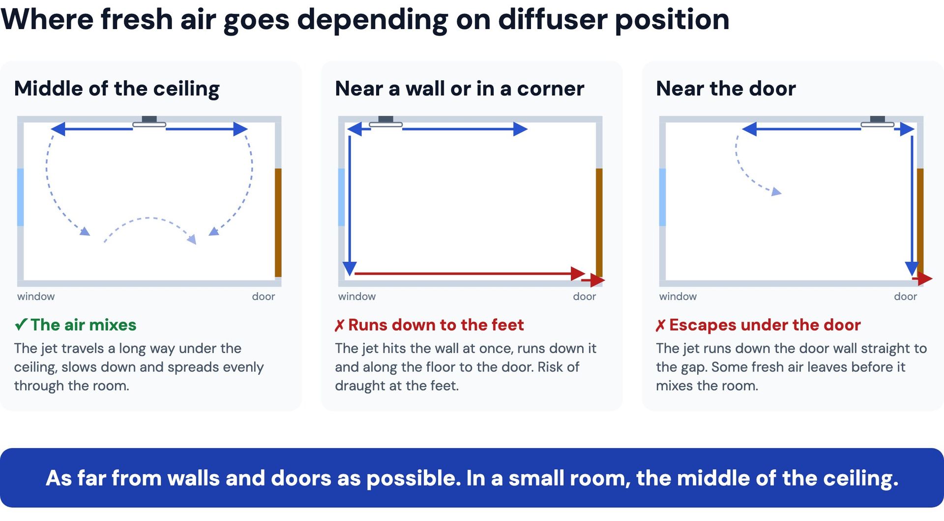
At the wall the jet turns downwards and runs down to the floor. It then continues along the floor to where the low pressure pulls it, which is the door and the gap under it. The extract is in the bathroom, toilet or kitchen, and air from the room reaches it under the door.
- fresh air travels along the floor past people and leaves the room before mixing it,
- there is cooler, faster air at your feet, which people feel as a draught,
- more stale air remains at head height.
What the simulation showed
We calculated the airflow in a 4.0 × 3.5 × 2.7 m room with one supply of 30 m³/h. The supply air was 21 °C, the room 23 °C, with a window on one wall and a door with a gap at the floor opposite. We put the supply in three places: the middle of the ceiling, the corner by the window 60 cm from two walls, and near the door 60 cm from the wall. We then added a tracer, like a dye, to the supply air and followed where it went in the first minutes.
| First 4 minutes | Middle | Corner | Near door |
|---|---|---|---|
| First fresh air under the door | after 99 s | after 68 s | after 35 s |
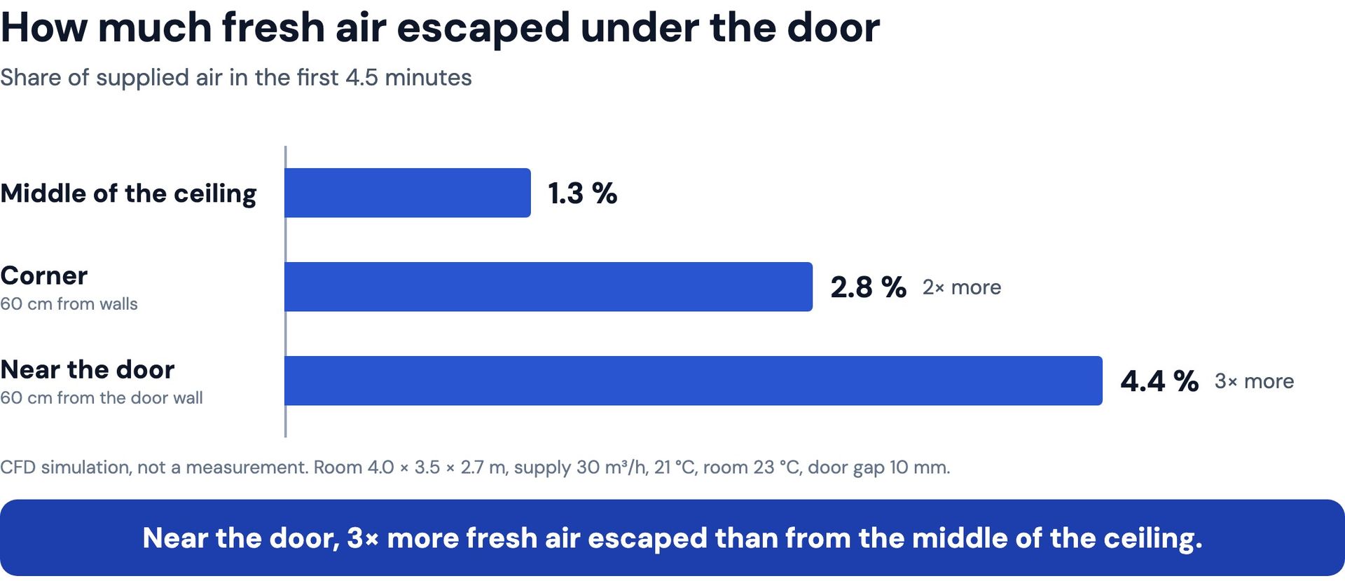
| Supplied air that left under the door (4.5 min) | 1.3 % | 2.8 % | 4.4 % |
| Fresh air at the feet / at standing head height | 4.2 / 4.8 % | 7.3 / 4.0 % | 2.8 / 5.0 % |
| Jet already returns from the wall at a distance from the supply of | 1.5 m | 0.7 m | 1.3 m |
| Draught risk DR, 95 % of the occupied zone | 2.1 % | 4.4 % | 1.8 % |
With perfect mixing, there would be 5.15 % fresh air everywhere after 4 minutes. The draught rate DR according to EN ISO 7730 gives the predicted share of people dissatisfied with draught.
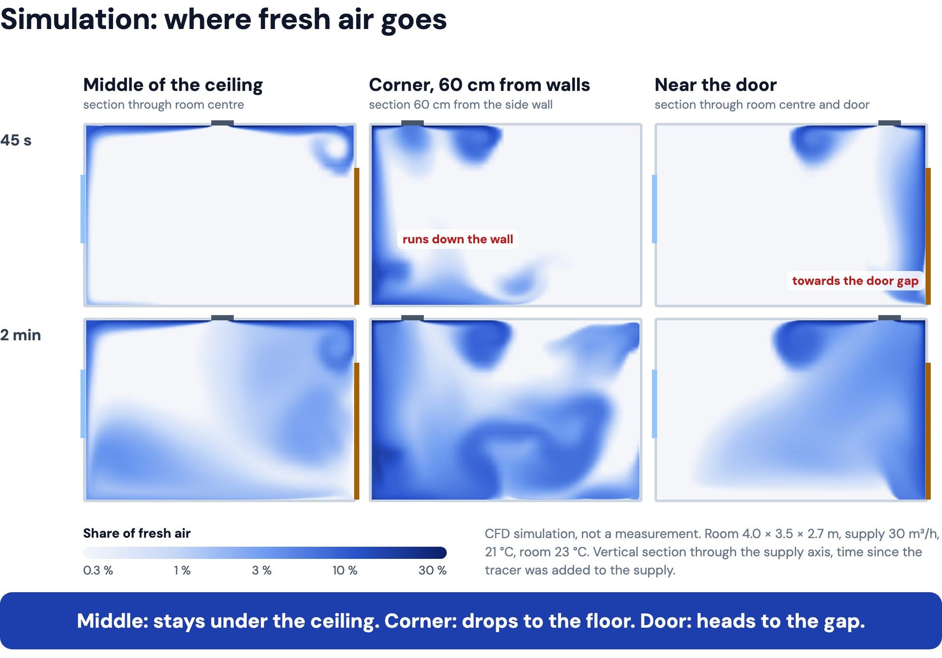
Middle: fresh air was spread most evenly by height and reached the door gap last.
Corner: the jet already returned from the walls 70 cm from the supply and ran down. There was almost twice as much fresh air at the feet as at head height, and the draught risk was twice as high. It is still low, but the difference was caused only by moving the supply.
Near the door: the draught did not increase, but fresh air started leaving under the door within the first minute. Part of the air warmed by the heat recovery unit passed through the room without any benefit.
Videos from the simulation
The first video shows the same room section as the image above, but over time. Blue is fresh air from the supply; the darker, the more of it there is.
Time since the supply was switched on, 4.5 minutes sped up 10×. Vertical section through the supply axis, window wall on the left, door wall on the right.
The second video follows individual air particles leaving the supply. You see the whole room from the side. The colour shows how long a particle has been in the room: dark blue ones have just left the supply, green and yellow ones have been in the room for several minutes.
The same three positions and the same time, sped up 10×. Near the door, notice how the particles drop to the floor by the door within the first minute.
How to place the supply in practice
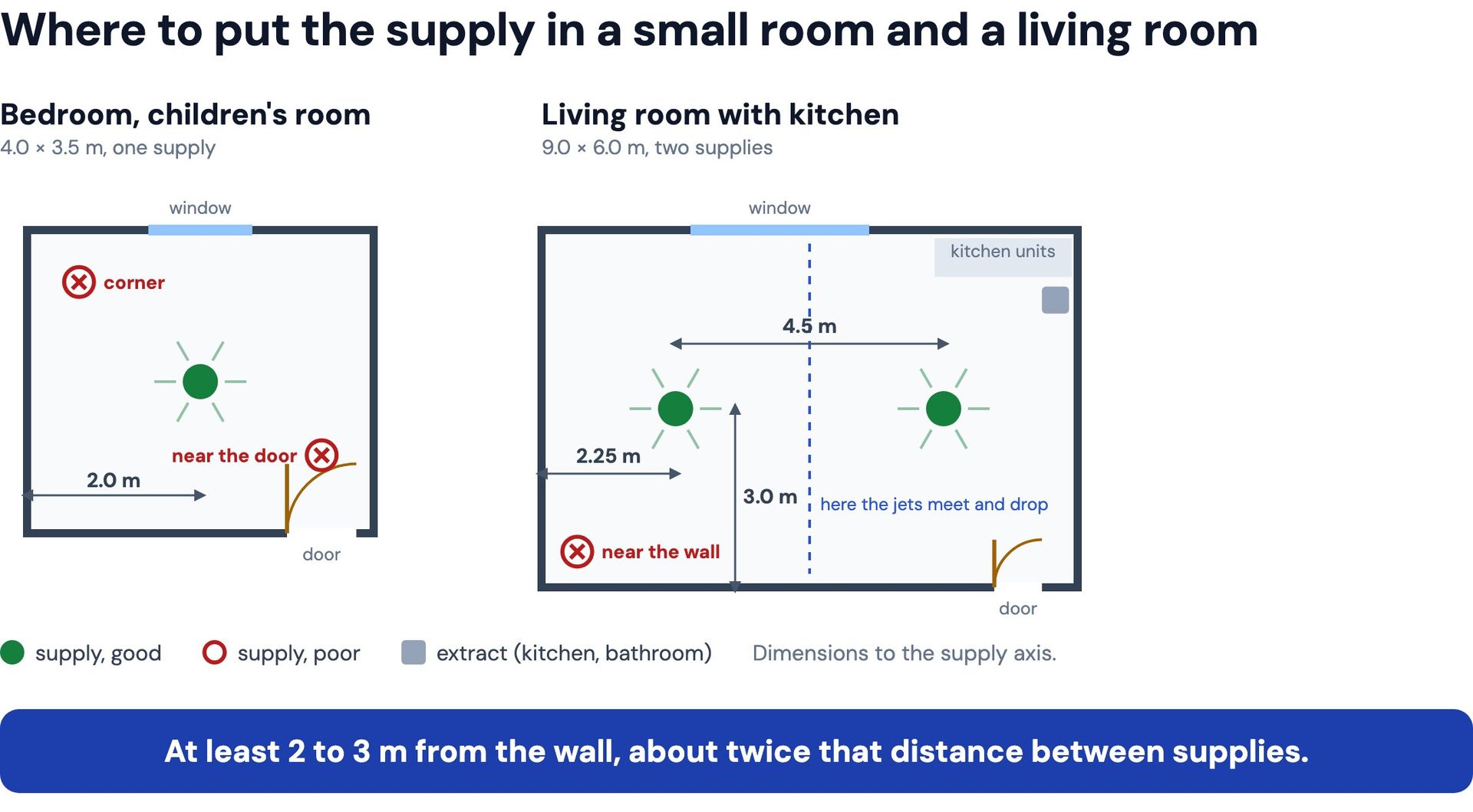
- Small room (bedroom, children's room, study): one supply as close to the middle of the ceiling as possible. If there is a light fitting, move the supply next to it, not towards a wall.
- Large room (living room with kitchen): several supplies, each at least 2 to 3 m from the wall. Space them evenly, roughly twice the distance from the wall. Where two jets meet, they behave much like at a wall and turn downwards.
- Far from the door. The door leads to the extract; a supply next to it is a short circuit.
- No obstacles under the ceiling. A tall wardrobe, a beam, a plasterboard step or a large light fitting in the path of the jet will detach it from the ceiling sooner.
- A supply near the window will not warm the cold glass. Cold air running down from the glass appeared in every position in the simulation. A good window and heating below it solve it, not the position of the supply.
What else matters
- Valve setting. A disc valve with a gap opened too wide, or a grille blowing diagonally downwards, does not use the Coandă effect. If the system allows it, regulate the airflow in the duct or in the plenum box, not by closing the disc.
- Airflow. At a higher airflow the jet reaches further, so a larger distance from the walls is needed. The manufacturer's throw data helps.
If you are looking for a diffuser with the regulator directly in the plenum box, see the plenum box with the Flow 125 diffuser.
Simulation is not artificial intelligence
The results in this article were not created by artificial intelligence. AI cannot calculate airflow; at most it can imitate a picture that looks plausible. We used an airflow simulation, technically called CFD (computational fluid dynamics).
Simulation software divides the room into hundreds of thousands of small cells. In each of them it solves the physical equations for the conservation of mass, momentum and energy. It calculates how the air flows, how it mixes, how the walls slow it down and how warmer air rises and cooler air sinks. In a time-dependent calculation it repeats this in steps shorter than a tenth of a second.
These are demanding calculations. One supply position meant more than 8,000 time steps, and in each one the equations are solved for all cells at once. The calculation ran in parallel on several processor cores and one position took about three quarters of an hour. Calculations with the full geometry of the valve have millions of cells and take even longer.
This lets us simulate what happens in reality very accurately. Aircraft, cars and ventilation systems are designed on the same principles. In addition, a simulation shows the air speed and temperature at every point of the room at once, which measurements could not capture.
Calculation conditions
| Room | 4.0 × 3.5 × 2.7 m, window on one wall, door with a 10 mm gap at the floor opposite |
|---|---|
| Supply | 30 m³/h, 21 °C, a generic jet along the ceiling, not a specific product |
| Room air | 23 °C, window glass 18 °C |
| Supply positions | middle of the ceiling; corner by the window, 60 cm from two walls; near the door, 60 cm from the wall |
| Calculation | time-dependent airflow calculation including temperature effects, first 4.5 minutes, 370 to 440 thousand cells |
The calculation does not include people, heat sources, open doors or complete mixing, which takes longer.
FAQ
Are these simulations made by artificial intelligence?
No. It is a physical airflow calculation that solves equations for hundreds of thousands of cells in the room. AI cannot do such calculations.
What if there is a light fitting in the middle of the ceiling?
Move the supply next to the light so that it stays as far from the walls and the door as possible. The jet should not hit a large pendant light straight away.
Does this apply to other brands of diffusers too?
Yes, if they guide the air along the ceiling. The simulation did not use a specific product but a generic air jet along the ceiling.
Isn't it better to put the supply by the window, where it is coldest?
No. Cold air runs down from the glass regardless of the supply position. In the simulation, the supply in the corner by the window brought the most fresh air to the feet and the highest draught risk.
How far from the wall at a higher airflow?
Further. The throw of the jet increases with airflow, so follow the manufacturer's throw data and use more supplies with a lower airflow each.